Client Objective: Manufacture a replacement propeller that fits seamlessly on an existing shaft — achieving “first-time-right” assembly and minimizing costly downtime.
In the marine industry, vessels rely on the efficiency and reliability of their propulsion systems. Propellers are critical components, but over time they can suffer damage due to normal wear, corrosion, or unexpected events such as grounding or collision. When such damage occurs, shipping companies must replace the propeller quickly to get the vessel back into service. Any delays or repeated rework in fitting new parts can result in significant financial losses, including missed schedules, higher repair costs, and idle vessels.
Although shafts are manufactured to SAE standards, real-world conditions introduce challenges. Manufacturing tolerances, combined with years of wear, may cause deviations from standard dimensions. This means that even a precisely manufactured replacement propeller may not fit properly if based only on nominal specifications. To eliminate the risk of misalignment or improper seating, the client sought a solution that would capture the true, as-is geometry of the existing shaft and propeller hub. They turned to V3D Technologies for advanced measurement and reverse engineering expertise.
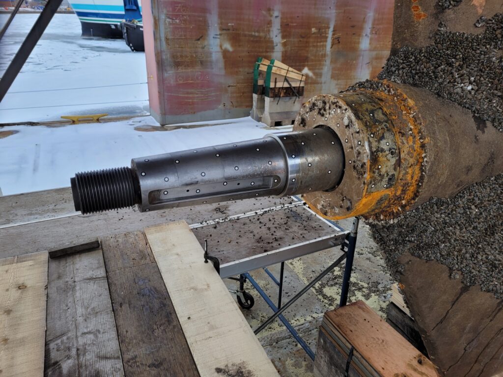
Propeller Drive Shaft
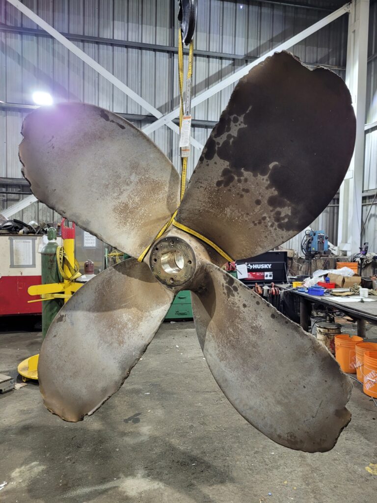
Damaged Propeller
Our Solution: On-Site, High-Accuracy Laser 3D Scanning & CAD Model
V3D Technologies mobilized a certified metrology-grade Laser 3D Scanner directly to the dock where the vessel was berthed. This approach avoided the need to dismantle or transport the shaft assembly, saving valuable time.
Step 1: High-Accuracy 3D Scanning of Propeller Hub
We started with placing positioning targets on the propeller hub. These targets allow the scanner to accurately track the object’s position during scanning.
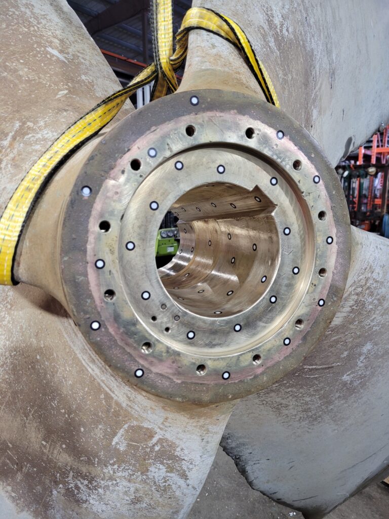
3D Scanning Positioning Targets on Propeller Hub
Next, we scanned the propeller hub and captured a high-resolution 3D mesh (polygon model) with all necessary details to extract required dimensions. Polygon models are not aligned to coordinate system when they are generated. Using geometric features such as planes and cylinders, the polygon model was aligned to coordinate system.
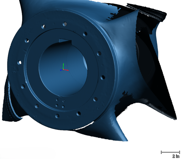
Polygon Model (scanned mesh) of Propeller Hub aligned to coordinate system
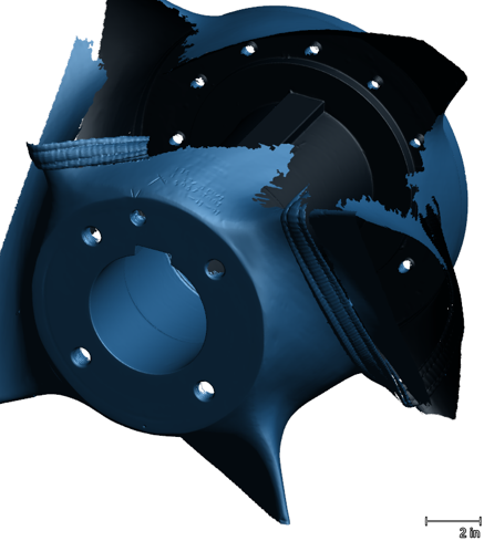
Polygon Model (scanned mesh) of Propeller Hub aligned to coordinate system
CAD Model construction of Propeller Hub
Aligned polygon model was transferred to advanced Scan to CAD Reverse Engineering software.
Initial Method: A revolve-based CAD model was created from a single cross-section of the taper. However, deviation analysis against the polygon model showed unacceptable dimensional variations.
Refined Method: Multiple cross-sections of the taper were extracted and lofted together to form a more accurate representation. This method produced a CAD model that closely matched the as-is geometry of the hub, ensuring precision far beyond standard nominal assumptions.
CAD model of Propeller Hub Taper constructed using multiple cross-sections and loft function
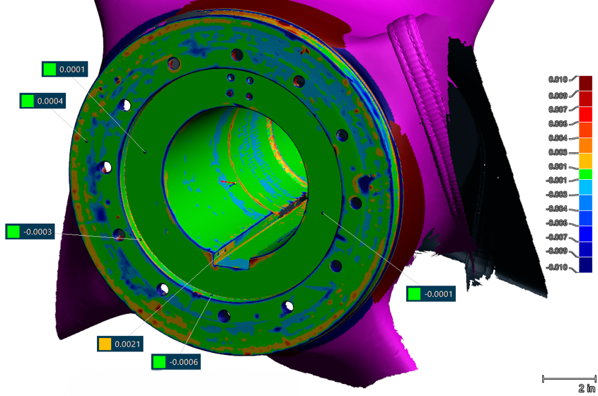
Deviation between CAD Model and Polygon Model of Propeller Hub
(shown on polygon model, in inches)
Deviation between CAD Model and Polygon Model of Propeller Hub
(shown on polygon model, in inches)
Deviation between CAD Model and Polygon Model of Propeller Hub
(shown on polygon model, in inches)
Deviation between CAD Model and Polygon Model of Propeller Hub
(shown on polygon model, in inches)
High-Accuracy 3D Scanning of Propeller Drive Shaft
We scanned the propeller drive shaft mounted on the ship directly and generated the polygon model.
Cylinder and planes were extracted from the polygon model. These entities were then used to align the polygon model to the coordinate system.
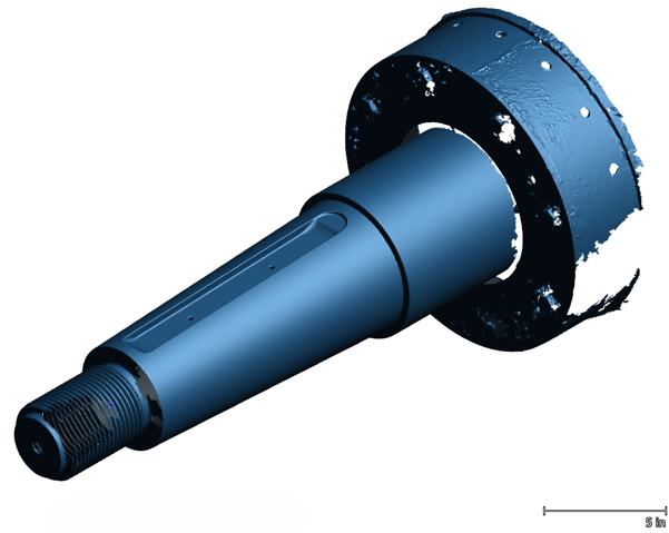
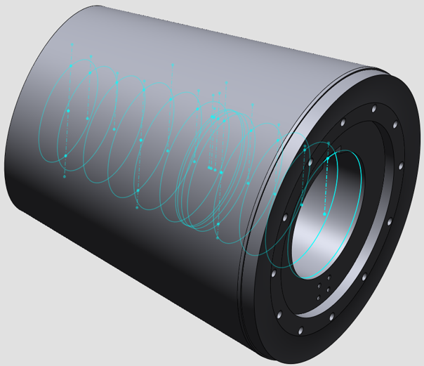
Polygon Model (scanned mesh) of Propeller Drive Shaft
CAD Model of Propeller Drive Shaft
Aligned polygon model was transferred to advanced Scan to CAD Reverse Engineering software.
- The shaft taper was first modeled using the revolve method, but the resulting deviations were outside acceptable tolerance.
- By applying the same refined loft-based method, we generated a CAD model that faithfully represented the shaft’s actual condition.
This second step ensured that both mating components – the propeller hub and the drive shaft were captured and reconstructed with exact accuracy.
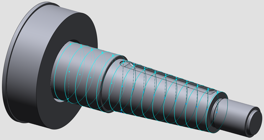
CAD model of Drive Shaft Taper created using multiple cross-sections and loft function
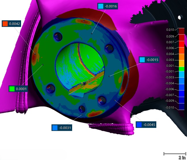
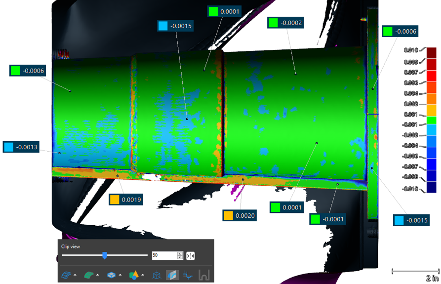
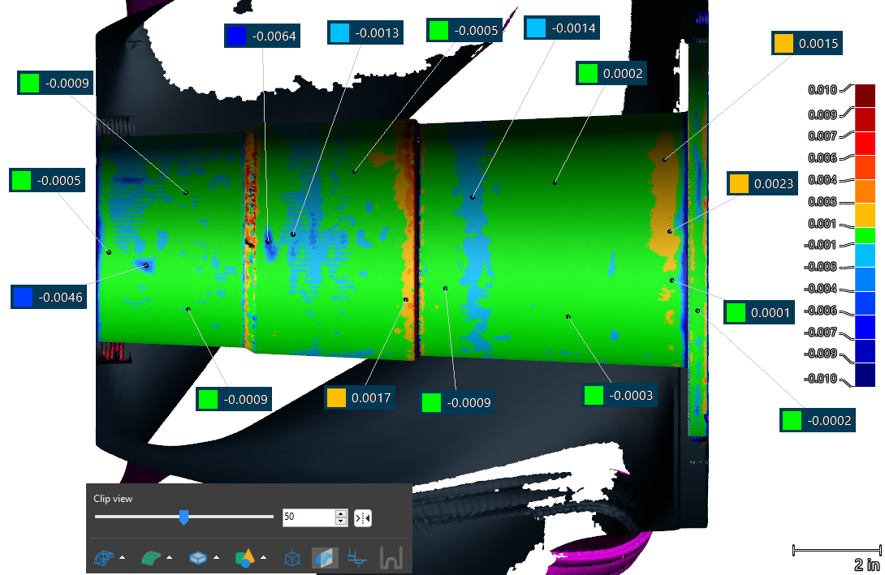
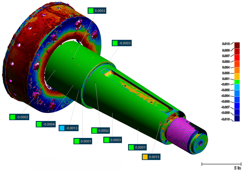 Deviation between CAD Model and Polygon Model of Drive Shaft
(shown on polygon model, in inches)
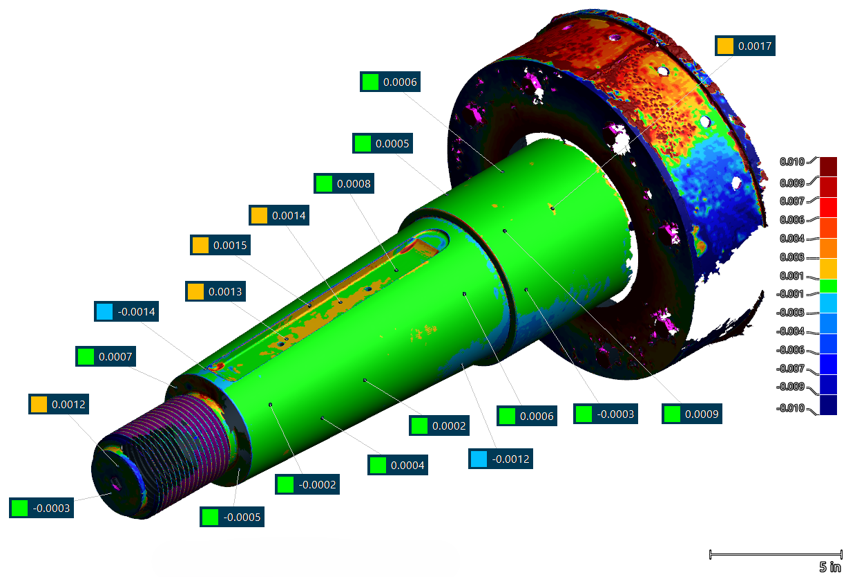
Deviation between CAD Model and Polygon Model of Drive Shaft
(shown on polygon model, in inches)
Results & Benefits Delivered
The combined scanning and reverse engineering processes produced fully accurate CAD models of the hub taper and the shaft taper. These models provided the shipyard and manufacturer with the critical data needed to fabricate a new propeller guaranteed to fit correctly on the very first attempt.
Key benefits achieved:
- Elimination of Guesswork: By relying on precise as-is data rather than nominal values, the risk of misfit was removed.
- Reduced Downtime: The replacement process was streamlined, minimizing disruption to the vessel’s operational schedule.
- Cost Savings: Avoiding multiple iterations of trial and error significantly lowered repair and manufacturing costs.
- Confidence in Fit: The client could proceed with manufacturing knowing the new propeller would integrate seamlessly with the existing shaft.
Conclusion:
This case study demonstrates how laser 3D scanning, and scan-to-CAD reverse engineering can transform the repair and replacement process in the marine industry. Propulsion system components such as shafts and propeller hubs, which experience years of service-related wear, often deviate from nominal specifications. Traditional measurement methods may overlook these variations, leading to costly mismatches.
By using advanced 3D scanning technology, V3D Technologies delivered highly reliable digital models that captured the true, real-world condition of critical parts. This ensured the new propeller could be manufactured with confidence, installed without error, and put into service immediately.
The outcome was not only a successful repair but also a demonstration of how modern 3D scanning significantly reduces risk, enhances precision, and optimizes turnaround time in marine operations. For shipping companies, this translates into operational reliability, reduced downtime, and measurable cost savings — a clear competitive advantage in an industry where every hour counts.