Preserving a Historic Machine Through Advanced 3D Scanning Technology
At V3D Technologies Inc., we regularly support clients with complex reverse engineering and 3D scanning projects across Ontario. One particularly unique project involved helping restore a vintage Koehring 305 Crawler and Truck Crane that had been part of a family-owned business since the 1970s.
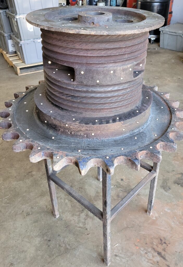
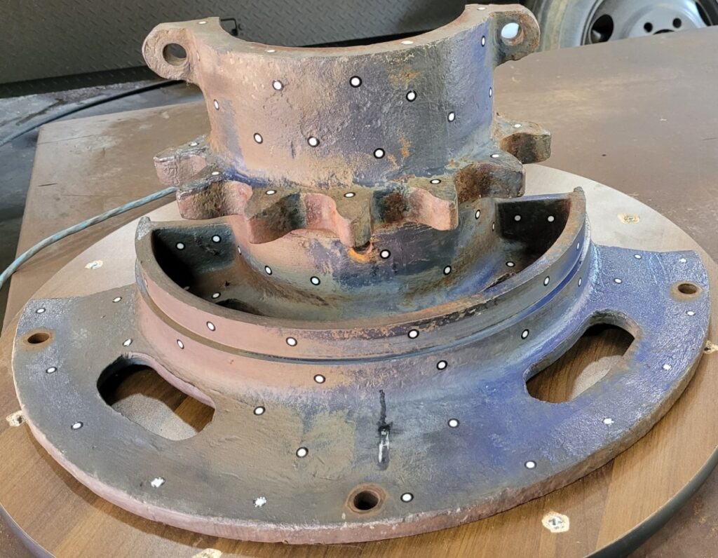
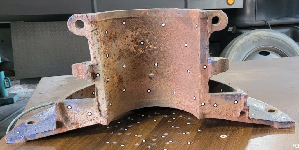
The machine held significant sentimental and historical value for the owner. However, after decades in storage, several critical components had been lost or discarded, including the Digging Drum and Sprocket Lagging assemblies. Without these parts, restoring the crane to operational condition was nearly impossible.
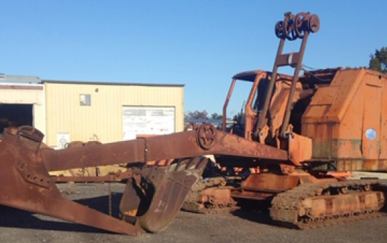
Vintage Koehring 305 Crawler and Truck Crane
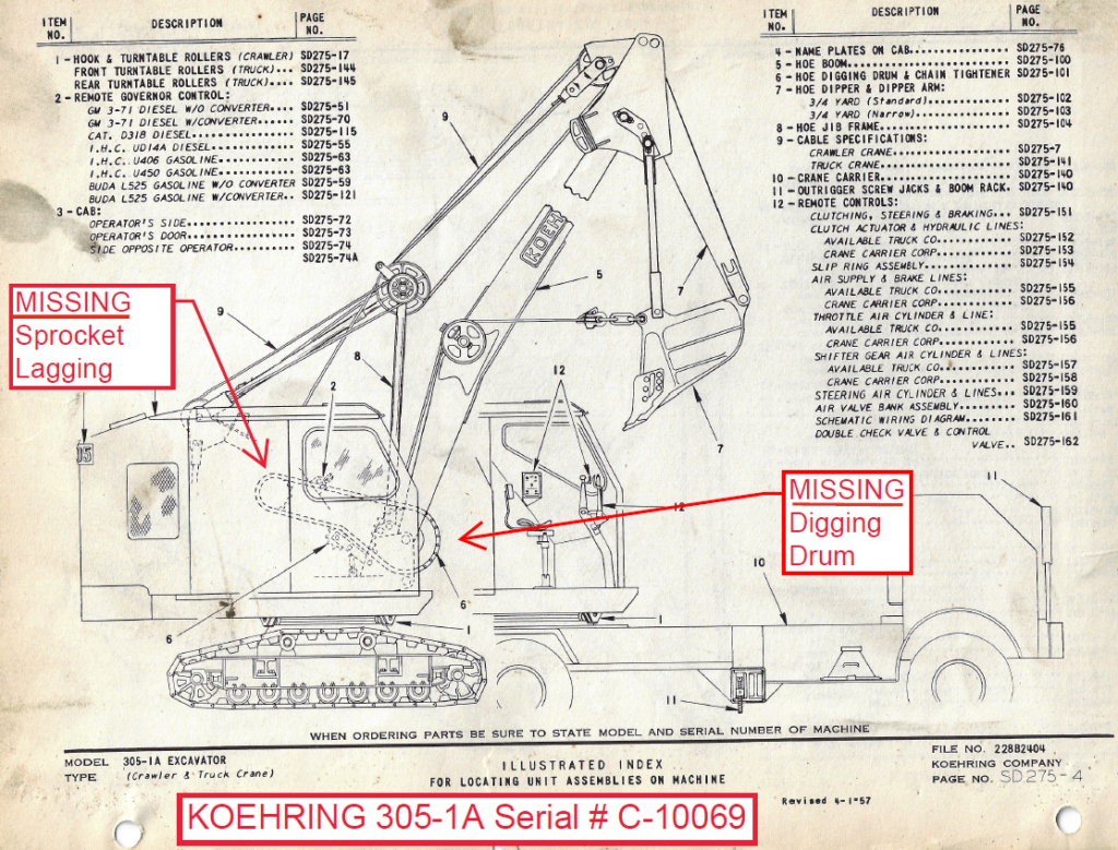
Schematic of Koehring 305 Crawler and Truck Crane
The client located an identical Koehring 305 machine near Ottawa, Ontario, and obtained temporary access to the missing components Sprocket Lagging and Digging Drum so they could be digitally captured and physically reproduced. V3D Technologies was selected to perform the laser 3D scanning, reverse engineering, CAD modeling, and engineering drawing creation required for manufacturing replacement parts.
This project demonstrates how laser 3D scanning and reverse engineering can be used to reproduce obsolete parts for heavy equipment and industrial machinery when original engineering documentation no longer exists.
Project Challenges:
Restoring legacy heavy equipment presents several engineering challenges:
- Original OEM drawings were unavailable
- Components had complex cast and machined geometry
- Existing parts showed wear, deformation, and age-related distortion
- High dimensional accuracy was required for functional reproduction
- Large components needed to be scanned completely and efficiently onsite
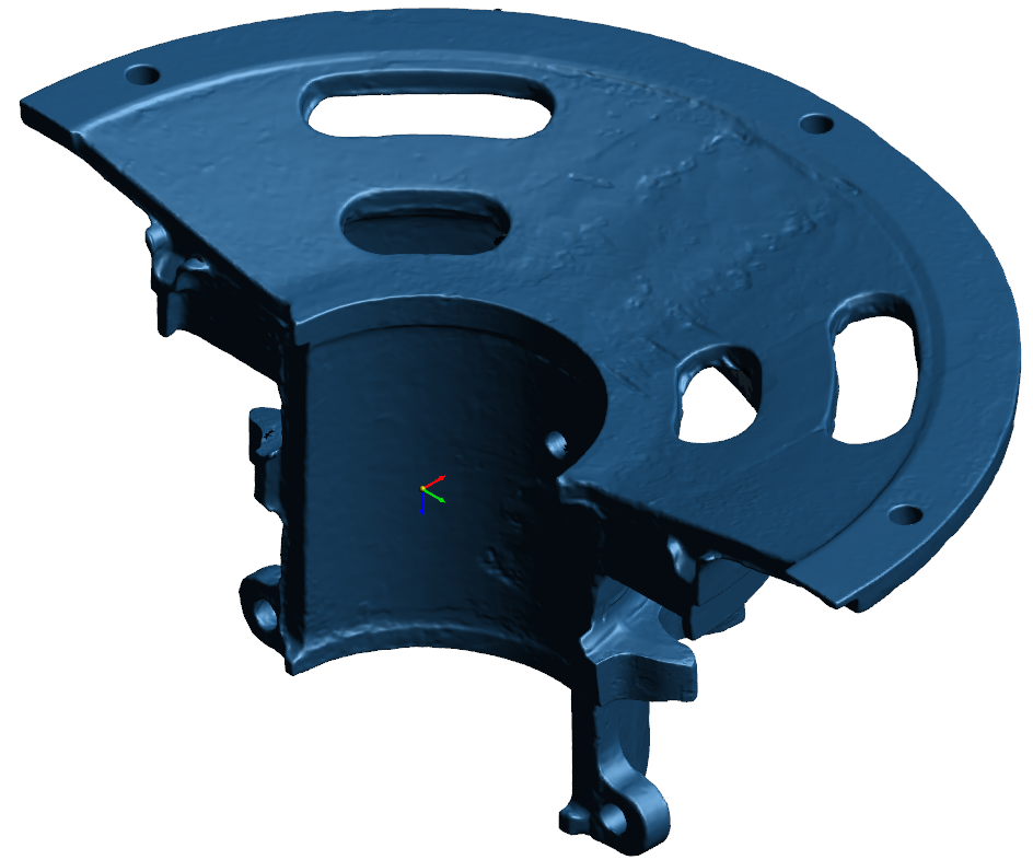
The Digging Drum included critical geometric features such as cable grooves, mounting surfaces, and cylindrical interfaces that required accurate digital reconstruction. The Sprocket Lagging components also contained irregular cast geometry and mating features that needed to align precisely during assembly.
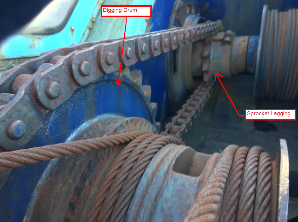
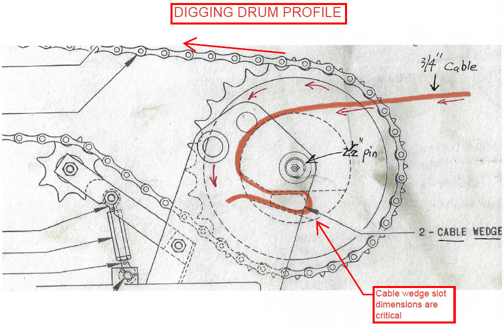
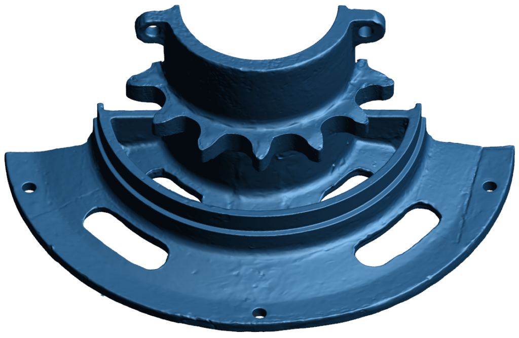
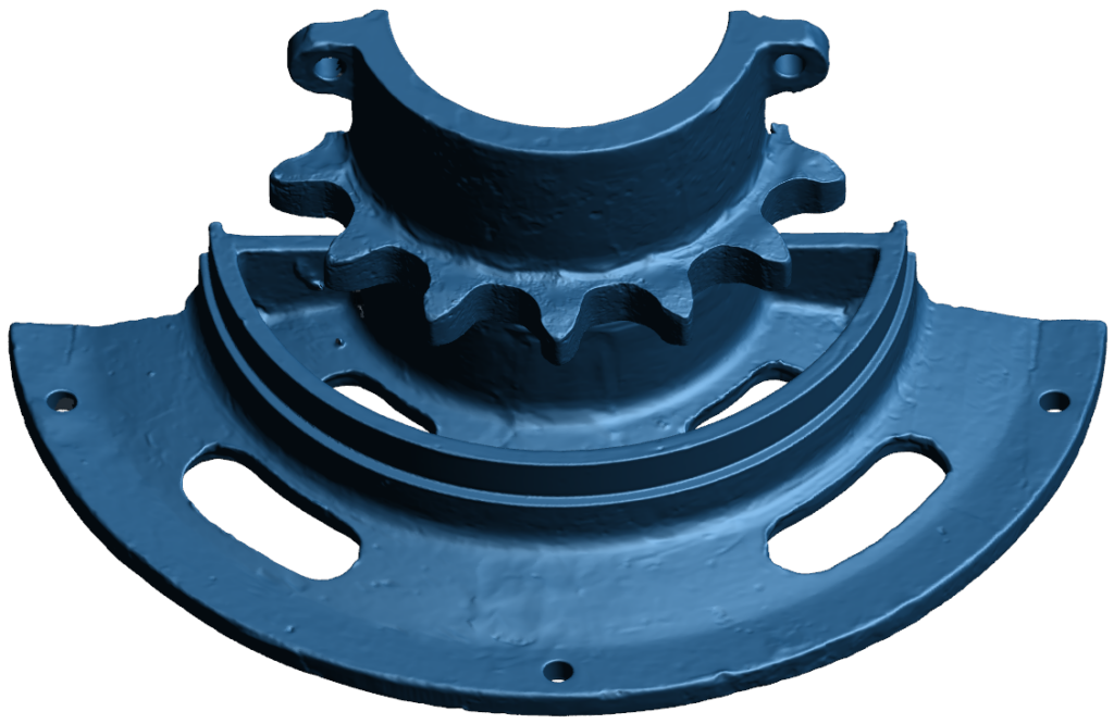
Details of Digging Drum and Sprocket Lagging
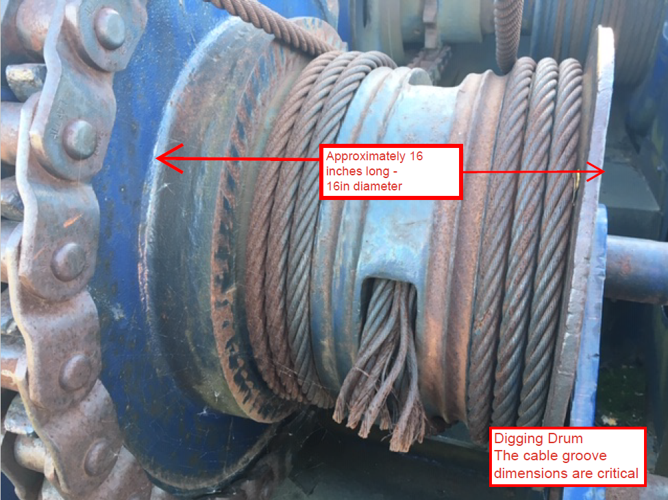
Size and Critical Features on the Digging Drum
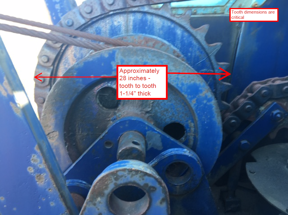
Diameter and Critical Features on the Digging Drum
Critical Dimensions & Features on the Digging Drum
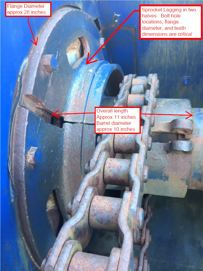
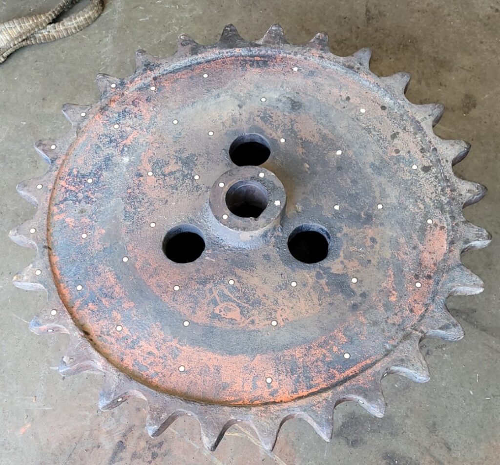
Size and Critical Features on Sprocket Lagging
Laser 3D Scanning and Reverse Engineering Workflow: High-Accuracy Onsite Laser 3D Scanning
To capture the required geometry with metrology-grade precision, V3D Technologies used the HandySCAN 3D Black Elite Scanner by Creaform. This handheld, portable scanner is ISO 17025 certified, metrology grade laser 3D scanner which provides micron level accuracy.
Our engineering team traveled onsite near Ottawa, Ontario to perform high-resolution 3D scanning of the original components.
Step 1 – Preparation and Target Placement
Positioning targets were strategically applied to the Digging Drum and Sprocket Lagging parts. These reference markers allowed the scanner to maintain precise tracking while scanning all surfaces of the components, including areas that required repositioning or flipping during acquisition.
This process ensured complete geometric coverage while maintaining high accuracy throughout the scan.
Digging Drum – Positioning Targets were applied on the part to scan it accurately and completely
Digging Drum – Positioning Targets were applied on the part to scan it accurately and completely
Step 2 – Polygon Mesh Generation and Alignment
Once scanning was completed, high-density polygon mesh models were generated from the captured scan data.
Because raw scan meshes are not inherently aligned to engineering coordinate systems, our team extracted geometric features from polygon model such as:
- Cylinders
- Planes
- Axes
These features were then used to align the scan data into meaningful coordinate systems suitable for reverse engineering and manufacturing. Accurate alignment is essential for creating usable CAD models and dimensionally reliable engineering drawings.
Polygon Model (scanned mesh) of Digging Drum aligned to coordinate system
Polygon Model (scanned mesh) of Digging Drum aligned to coordinate system
Step 3 – Reverse Engineering and Scan-to-CAD Model Development
The aligned polygon meshes were imported into Geomagic Design X which is an advanced Scan-to-CAD reverse engineering software.
Using extracted geometry and cross-sectional analysis, V3D Technologies created fully parametric CAD models of the missing components.
For the Digging Drum, this included:
- Creating constrained parametric sketches
- Reconstructing cable groove geometry
- Generating accurate helical paths
- Building revolve and sweep features
- Reproducing mounting and interface geometry
The final CAD model accurately represented the original component while removing inconsistencies caused by wear and deformation accumulated over decades of service.
Cross-section extracted from polygon model for revolve feature. Note that the cross-section is fully parametric and constrained
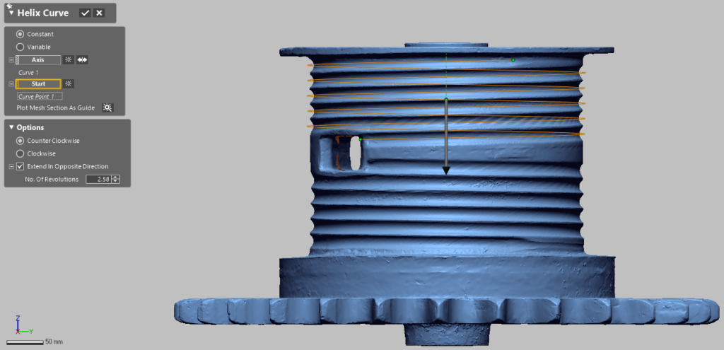
Parametric Helix Curve used to Sweep Cross-Section to create cable groove
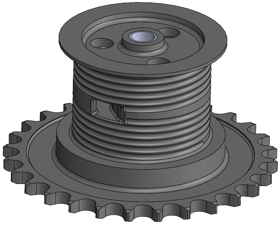
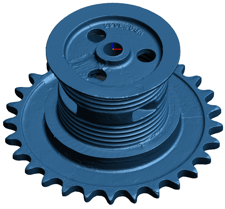
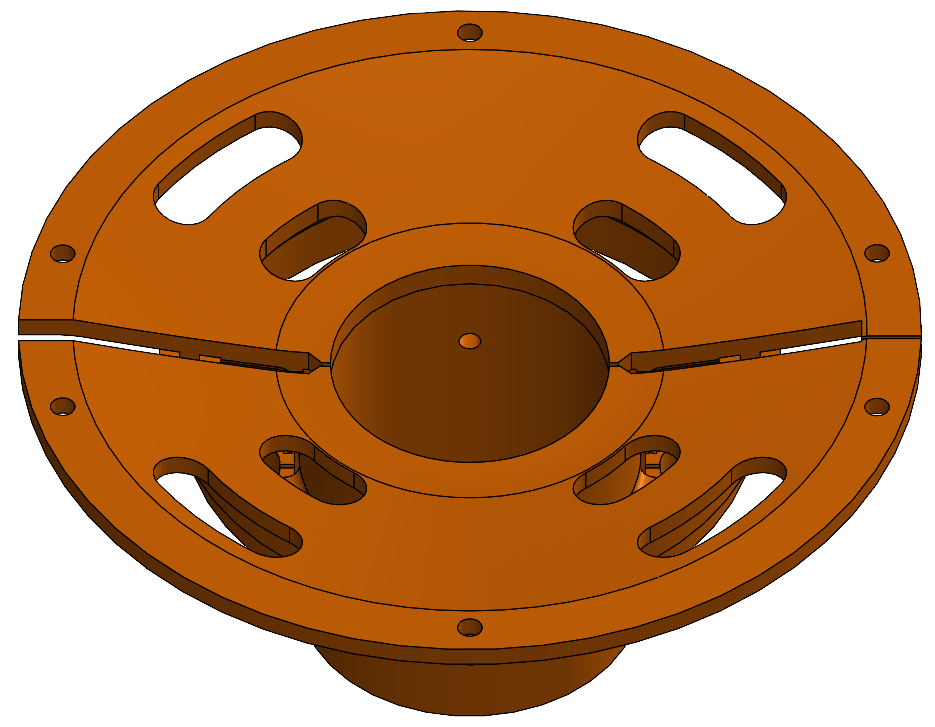
Parametric CAD model of Digging Drum
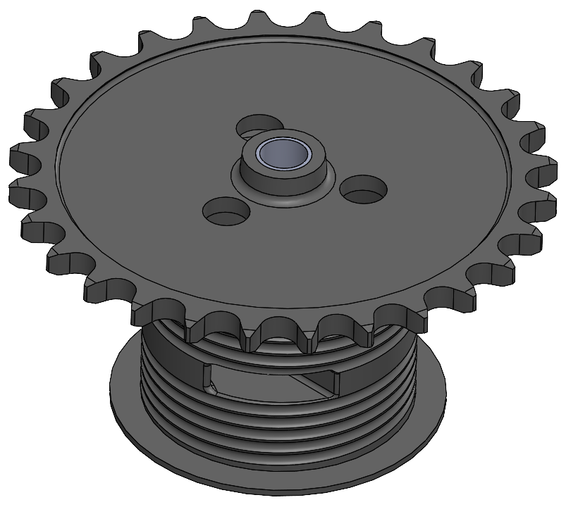
Parametric CAD model of Digging Drum
Step 4 – CAD-to-Scan Deviation Analysis
To validate model accuracy, V3D Technologies performed detailed CAD-to-mesh deviation analysis.
This process compared the mathematically perfect CAD geometry against the scanned polygon mesh data to identify dimensional variation across the component surfaces.
Because the original parts had experienced years of operational wear, certain localized deviations were expected and acceptable. The deviation analysis helped verify that the engineered CAD models maintained dimensional integrity while compensating for damaged or distorted areas. It also helped to confirm that no feature was missed on the CAD model mistakenly.
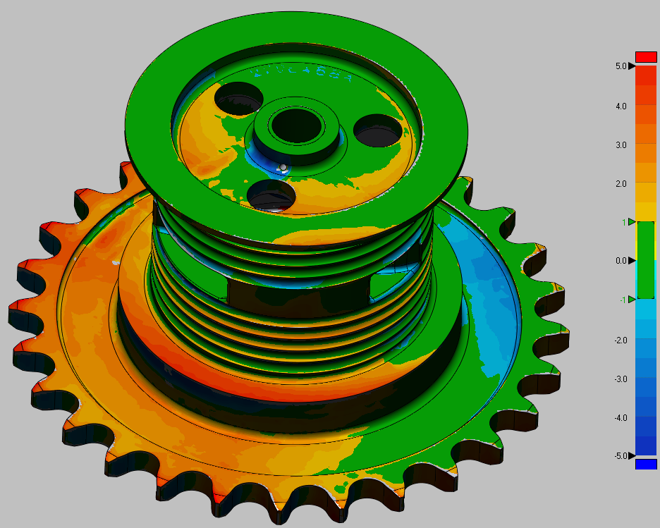
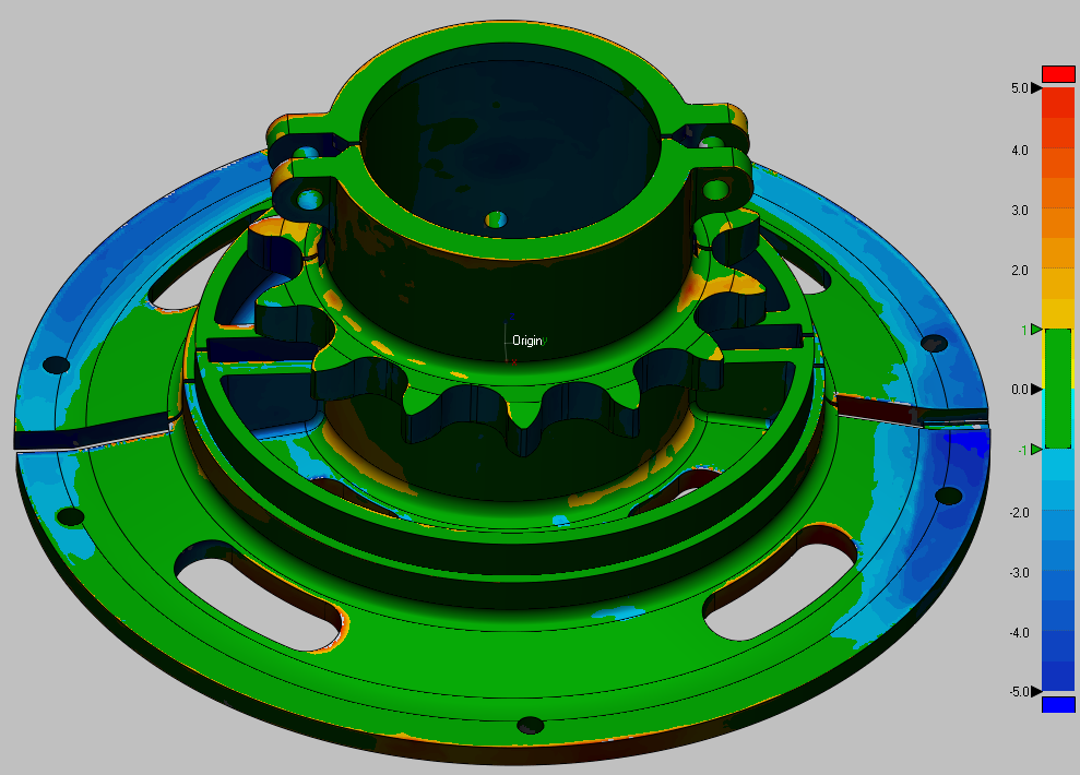
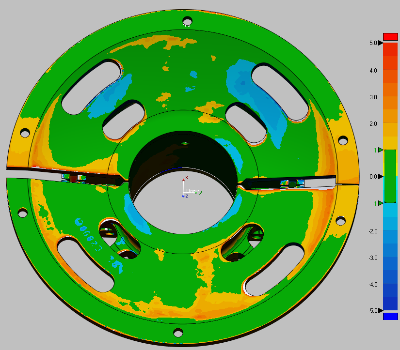
Deviation between CAD Model and Polygon Model of Digging Drum
(shown on CAD model, in mm)
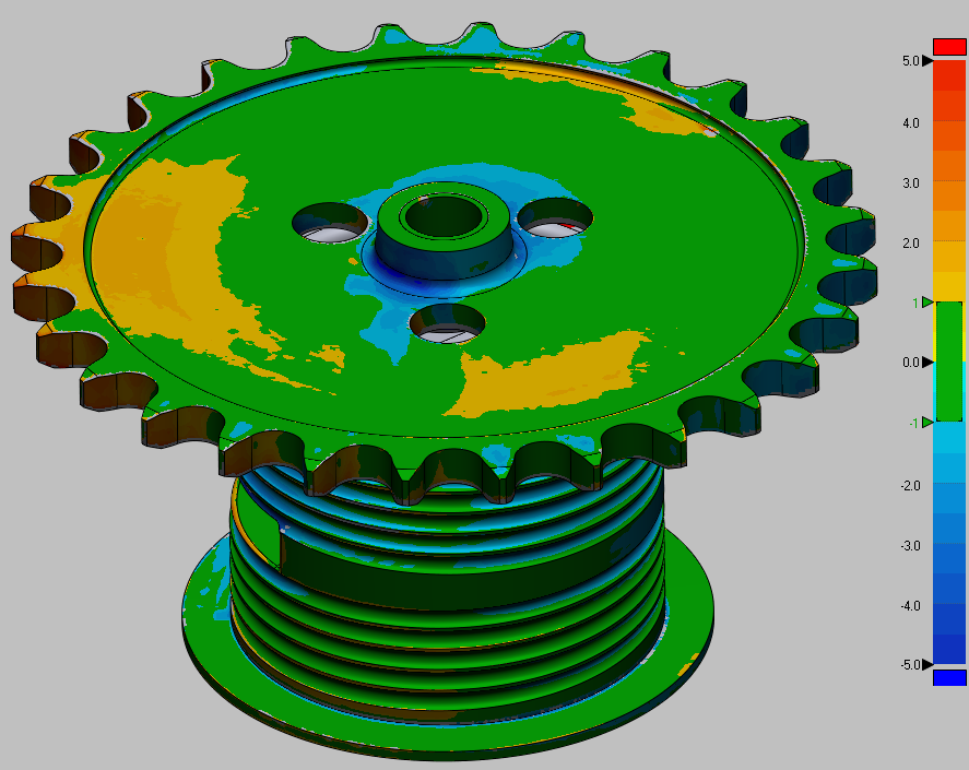
Deviation between CAD Model and Polygon Model of Digging Drum
(shown on CAD model, in mm)
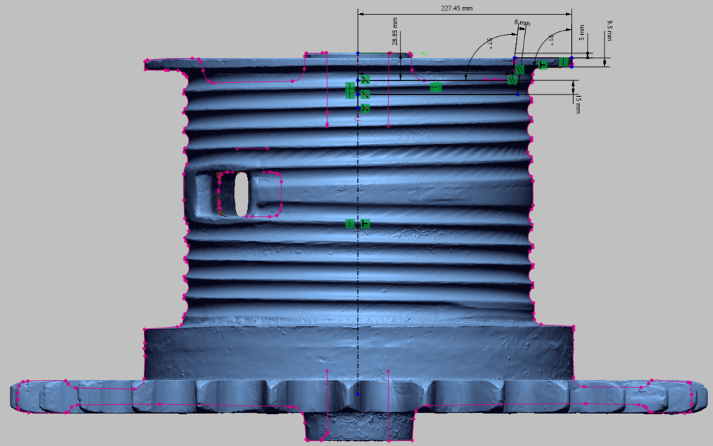
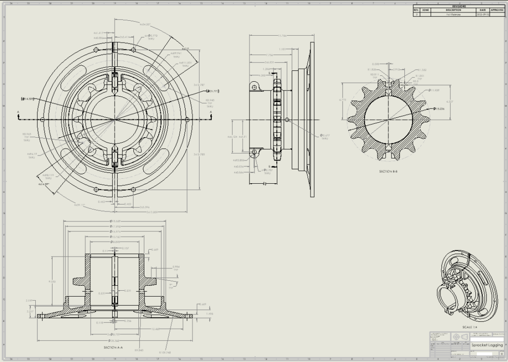
Step 5 – Manufacturing-Ready Engineering Drawings
After CAD validation was completed, detailed 2D engineering drawing of Digging Drum was created in Solidworks for manufacturing purposes.
The drawings included:
- Critical dimensions
- Cross-sections
- Feature callouts
- Datum structures
- Assembly interfaces
- Machining details
These deliverables enabled the client to move forward with accurate reproduction and fabrication of the missing components.
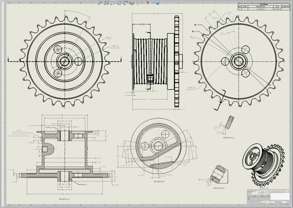
2D Engineering Drawing of Digging Drum
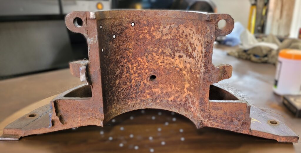
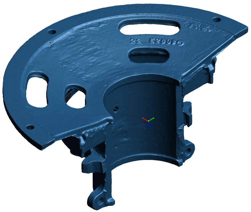
Reverse Engineering the Sprocket Lagging Assembly
The Sprocket Lagging assembly consisted of two separate halves that functioned together as a single casting assembly within the machine.
Each half was individually scanned and processed before being digitally assembled in CAD.
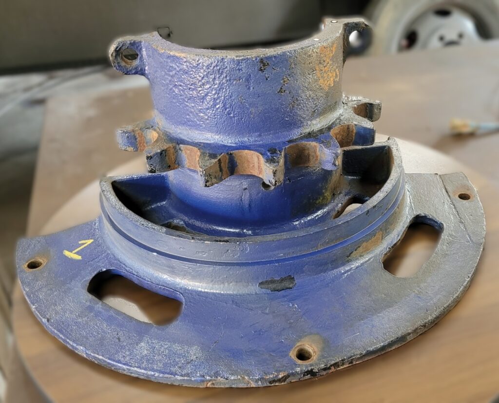
One Half of Sprocket Lagging part
One Half of Sprocket Lagging part
 Polygon Model of one half of Sprocket Lagging
Polygon Model of one half of Sprocket Lagging
Other half of Sprocket Lagging part
Other half of Sprocket Lagging part
Polygon Model of other half of Sprocket Lagging
Polygon Model of other half of Sprocket Lagging
Polygon Model Analysis
Through measurement and analysis, V3D Technologies determined that the original design was likely manufactured as a single casting and later separated into functional halves for installation and maintenance purposes.
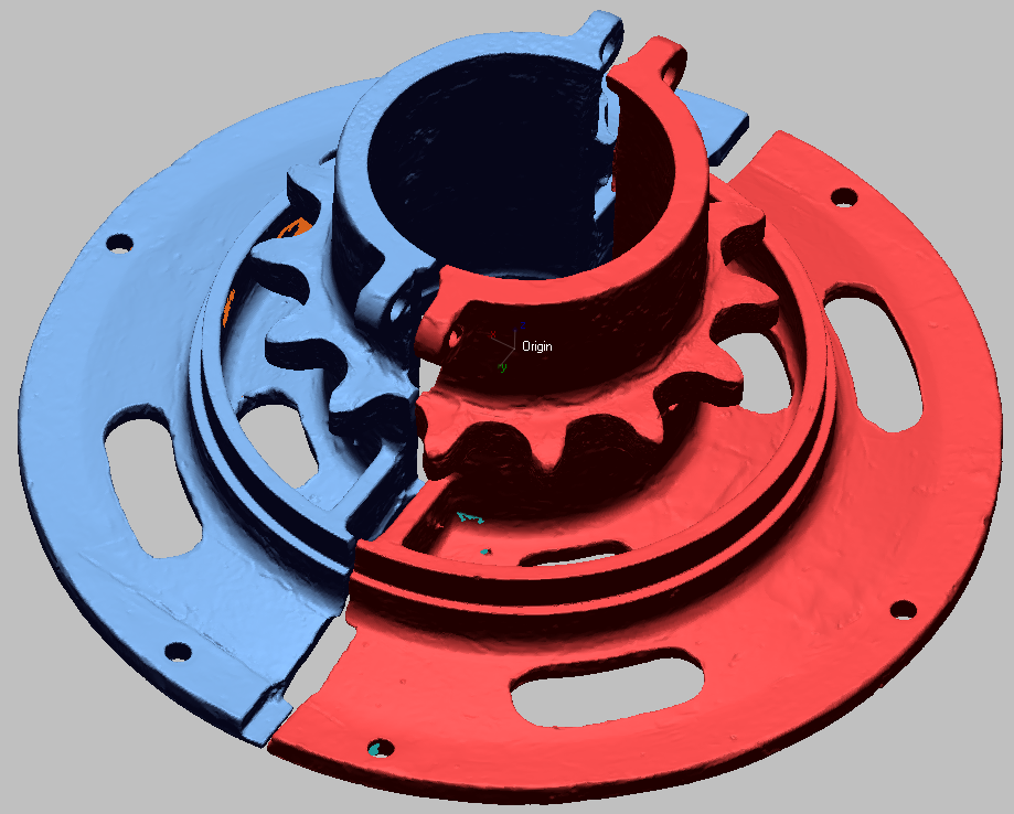
Alignment & Assembly of polygon models of 2 halves of Sprocket Lagging
Based on discussions with the client, a unified CAD model was created with split features incorporated into the final design for manufacturing flexibility.
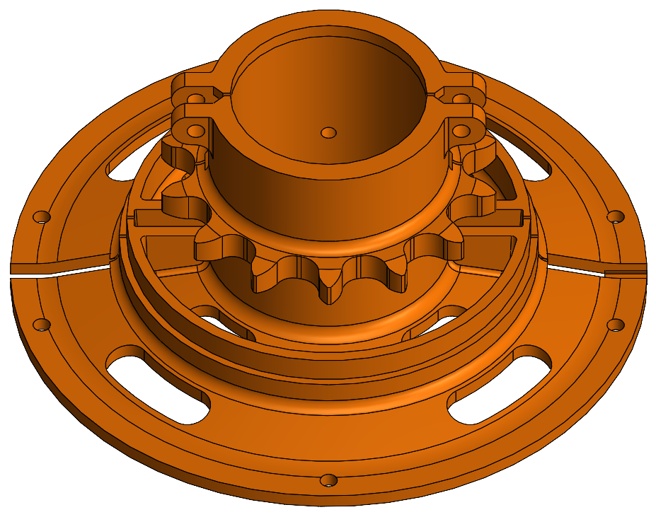
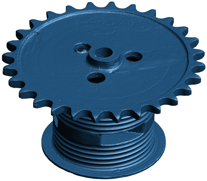
3D CAD model of Sprocket Lagging
3D CAD model of Sprocket Lagging
Deviation analysis was done between CAD Model and Polygon Model of Sprocket Lagging.
Deviation between CAD Model and Polygon Model of Sprocket Lagging (shown on CAD Model, in mm)
Deviation between CAD Model and Polygon Model of Sprocket Lagging (shown on CAD Model, in mm)
2D Engineering Drawing
Next, we created an engineering drawing for the Sprocket Lagging using the CAD model. Part was completely defined for all manufacturing dimensions using different views and cross-sections.
2D Engineering Drawing of Sprocket Lagging
Results Delivered:
V3D Technologies successfully delivered:
- High-accuracy laser 3D scanning services
- Complete polygon mesh models
- Scan to CAD Parametric CAD models
- CAD-to-mesh deviation analysis reports
- Manufacturing-ready 2D engineering drawings
- Reverse engineered data for obsolete heavy equipment components
The client was able to proceed with manufacturing replacement parts and continue the restoration of the historic Koehring 305 machine.
Why 3D Scanning is Ideal for Restoration Projects:
Laser 3D scanning and reverse engineering are highly effective solutions for restoring obsolete industrial equipment when original drawings no longer exist.
Benefits include:
- Accurate digital preservation of legacy components
- Faster reproduction of discontinued parts
- Reduced manual measurement errors
- Improved fitment verification
- Creation of long-term digital archives
- Support for custom manufacturing and restoration
At V3D Technologies Inc., we specialize in high-accuracy 3D scanning, LiDAR scanning, reverse engineering, and 3D metrology services for industrial, automotive, heavy equipment, aerospace, and manufacturing applications across Ontario and Canada.
Looking for Laser 3D Scanning or Reverse Engineering Services?
Whether you need to reproduce obsolete parts, restore legacy equipment, or generate CAD models from physical components, V3D Technologies Inc. can help.
Our services include:
- Laser 3D Scanning
- Portable Metrology
- Reverse Engineering
- Scan-to-CAD Modeling
- 2D Engineering Drawings
- CAD-to-Scan Inspection
- LiDAR Scanning
- Industrial Measurement Services
Visit V3D Technologies Inc. to learn more about our engineering and 3D scanning solutions.