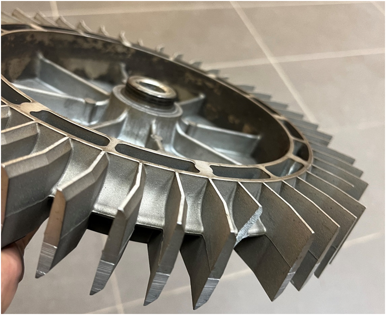
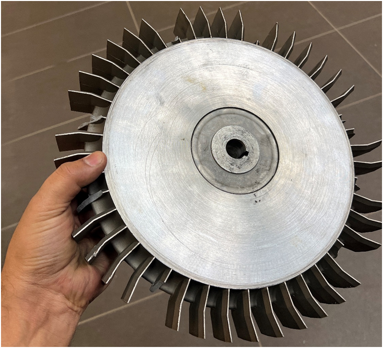
The Challenge: Often legacy parts don’t have drawings and CAD models to produce their replacements. One of our customers experienced a similar situation with a 21” diameter impeller. After years in service, the blades of a legacy impeller broke. A replacement part had to be produced, however, no CAD model or engineering drawing was available in the MRO department. The impeller runs within tight clearances in the casing. Impeller blade geometry was complicated to measure using traditional methods to produce an accurate CAD model and eventually a replacement part that could run within the tight clearances.
The Solution: We helped our esteemed client manufacture a replacement impeller by producing an accurate CAD model from a 3D scan of the broken part. A certified metrology-grade laser 3D scanner was used to accurately scan the broken impeller.
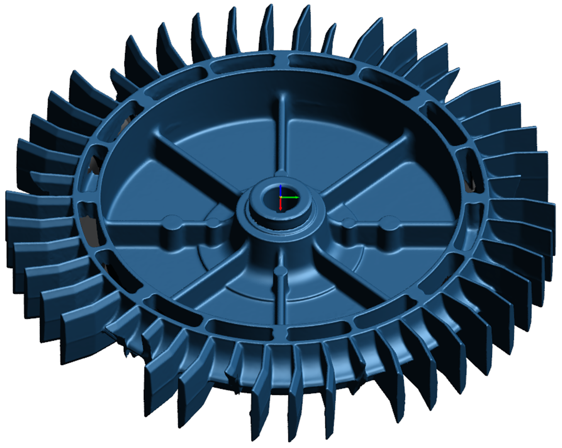
Polygon Model (scanned mesh) of broken Impeller
Polygon Model (scanned mesh) of broken Impeller
As a first step, the polygon model generated by the scanner was aligned to the global coordinate system in VXmodel software.
Next, the aligned polygon mesh was transferred to Geomagic Design X scan to CAD reverse engineering software. Design X helps create accurate parametric CAD models using the polygon model (scanned mesh). Here we created cross-sections referencing the polygon mesh and created a parametric CAD model for the impeller. Each cross-section was fully constrained with dimensions and geometric relations. The deviation of each cross-section concerning scanned mesh was analyzed to ensure the highest accuracy of the CAD model. These deviations likely arise from manufacturing variation and wear in scanned part due to prolonged operation under high-stress conditions as compared to mathematically perfect CAD entities. The request from the customer was to create a “design intent” CAD model i.e. round off feature dimensions to one or two decimal places after extracting them from the polygon model (scanned mesh).
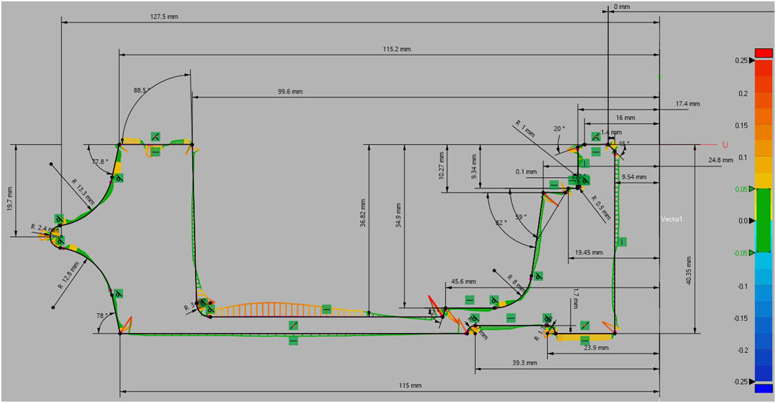
Deviation Analysis of Cross-Section used for creating Impeller Body
Deviation analysis of the complete CAD model was done and presented to the customer for acceptance. The customer was explained the reasons for the deviations between the scanned mesh and the mathematically perfect CAD model. Deviation analysis also helps to check if any CAD model feature is completely missing or grossly out of location as compared to scanned mesh.
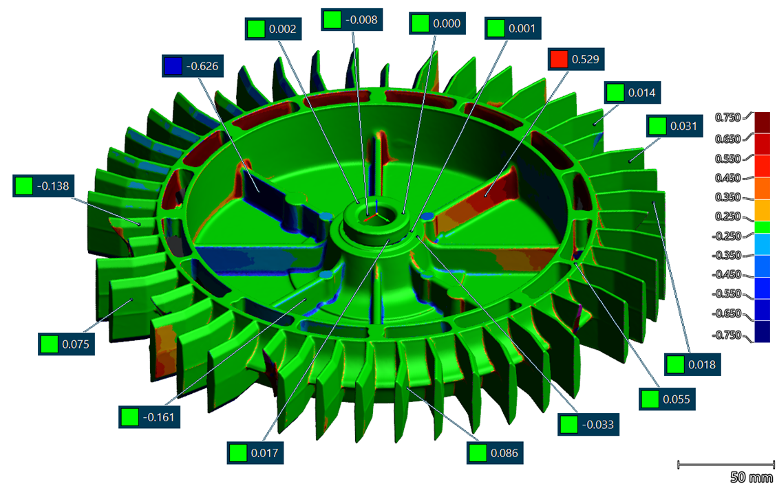
Deviation between CAD model and Polygon model (scanned mesh)
(shown on polygon model in mm)
Positive Deviation Values: CAD model at LMC wrt to scanned mesh
Negative Deviation Values: CAD Model at MMC wrt to scanned mesh
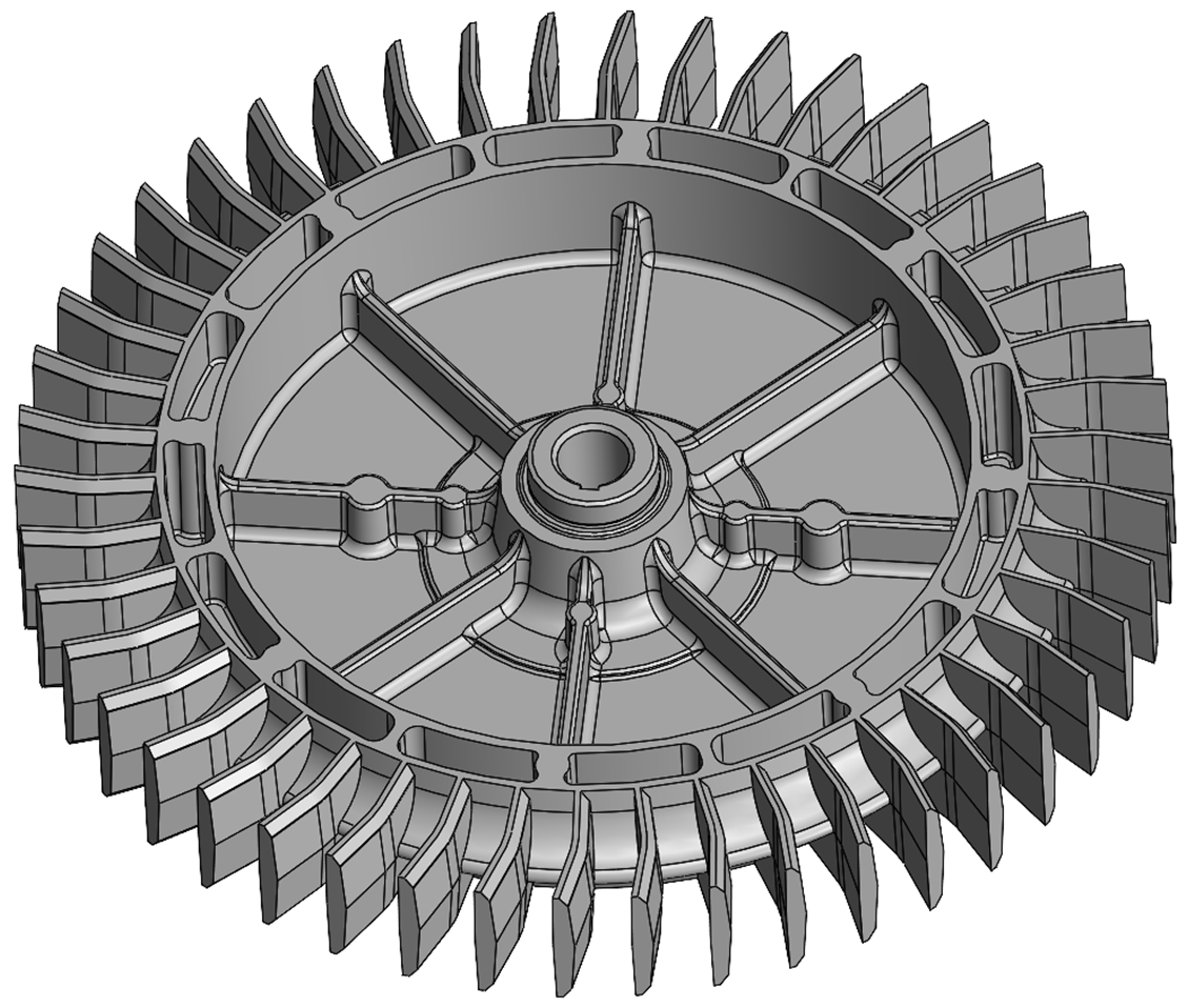
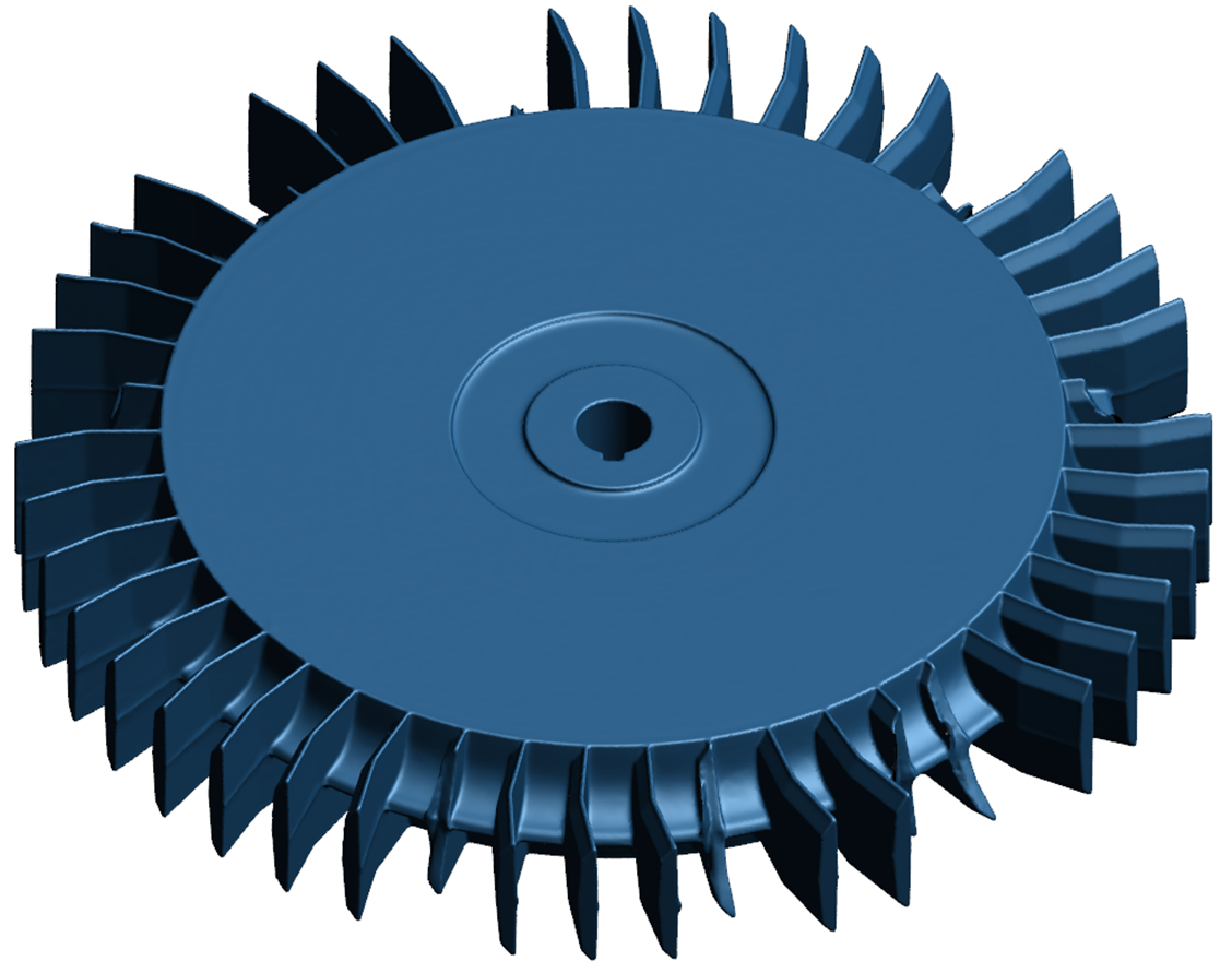
CAD Model of Impeller
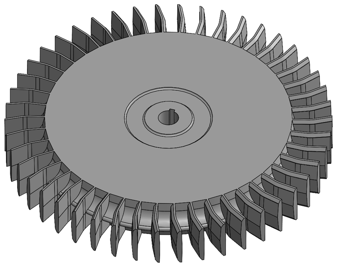
CAD Model of Impeller
Conclusion:V3D Technologies was able to provide the CAD model for the impeller in a very short time. The customer was able to get the impeller made using the provided CAD model, complete the replacement, and continue with the operations with the least downtime. With its fast turnaround time & high accuracy, V3D Technologies is the choice for MRO departments of various manufacturing & operations companies to get their legacy parts 3D scanned and reverse-engineered to ensure the least downtime and maximum efficiency.